ELECTRONICS CORNER
My Repair Jobs

|
Job Number |
|
0201-36 |
|
|
|
|
|
|
||
|
Equipment type |
|
Video Recorder |
||
|
|
|
|
||
|
Maker + Model # |
|
Sanyo VHR 5200 G |
||
|
|
|
|
||
|
Made in |
|
|
|
|
|
|
|
|
||
|
Comments |
|
|
||
BAD |
1 |
Fast Forward and Rewind
does not function |
|
|
|
|
|
|
2 |
No Display (in complete
darkness some light could be seen, but flickery) |
|
|
|
|
|
|
|
|
GOOD |
1 |
Powers up, and good
Play, Rec, Cue, etc functions |
|
|
|
|
|
|
2 |
Good picture and sound
output |
|
|
|
|
Full repair description and observations |
|
|
|
|
|
FAULT 1: - No display
(Flourescent vaccum type) |
|
|
|
|
|
1 |
I noted dismantled the
front section of the video, were I could make tests on the pins of the vacuum
display. I noted that there were 2 main pins, (probably the voltage supply)
and a set of pins where each corresponded to a particular segment/icon
display. In fact the latter set came from a large IC (u-processor / display
driver?) while the other two came from a different source. Following their
path, these 2 pins came from the power supply section. Touching these 2 pins
to earth via a 100 Ohm resistor caused the display to light up a little more |
|
|
|
|
2 |
I opened the power
supply compartment, which revealed that it was a switch mode power supply
type. The particular pins that were being tracked came directly from a
rectifying diode and filtering capacitor. From the SMPS. But there were other
observations. The filtering capacitor was punctured, and the PCB was
previously altered in this area by a previous technician. |
|
|
|
|
3 |
I replaced the capacitor
but I came to a problem. The polarity! The original faulty capacitor was
connected with the +ve side at the earth and the –ve side with the diode. I
assumed that the previous technician connected it in the wrong place and so I
placed it the other way round. I also changed the rectifying diode – a 1n148.
On powering, the result was worse. The capacitor began to produce white fumes
within seconds. I turned the capacitor in the original position (+ve to
earth, -ve to diode) and on powering the capacitor did not fume, and the
display lighted up. The supply produced was of –50V |
|
|
|
|
4 |
After few trials, the
display went off again. The diode opened up. I checked from Maplin databook
the diode and it was a signal diode with maximum rating of 50V. I needed a
more powerful rectifying diode. I found out that the 1N400x series is the
appropriate choice of rectifying diodes. I found an old 1n4004 (200V max
rating) but strangely enough, it went open after some days. |
|
|
|
|
5 |
I went to HE, and he
advised me a 1N4007 – the stongest of the diode family. I replaced it and the
display was OK. However I noted sparks of shorts in the chassis, which was
bad ridden, burrowed and manipulated by the previous technician. The short
was between a +66V from one track, and the –50V from a very near track. I
opened the –50V track and used a wire to supply the voltage near the plug
area. No sparks were now seen and it could be said the finally the display
fault was fixed once for ever.
Probably, these pcb shorts caused the 1N004 diode to blow. |
|
|
|
|
FAULT 2: - No Fast
Forward or Rewind |
|
|
|
|
|
1 |
This fault was solved by a
little luck and good observation. Will
operating the FF / REW I was observing the mechanism, and noted that the
position of a particular small lever was actually without function and
useless. |
|
|
|
|
2 |
Marks of friction on a
neighbouring metal part showed that the gear has slipped. With effort I
placed the gear in the expected original position and the FF and REW came to
work well. |
|
|
|
|
3 |
Unfortunately during the
process I lost the timing and the Player was ejecting the video tape. |
|
|
|
|
Fault 3: Timing of the
mechanism and control step-mode motor |
|
|
|
|
|
1 |
First I changed the
timing belts. There were just 2 to change. The large one around the capstan
motor and was very easy to replace, and a small one around the step mode
motor, which was quite difficult to replace. |
|
|
|
|
2 |
The video was set to
stop mode by rotating manually the step motor until the T and S poles are in
the full backward position. |
|
|
|
|
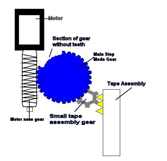
3 |
Remove the metal casing
over the step motor, motor nose gear and main gear. |
|
|
|
|
3 |
By means of a
screwdriver move the tape loading assembly completely to the back side.
Usually it will be by about 4 or 5 gear teeth ahead. It must be moved
manually back to the last gear. |
|
|
|
|
4 |
The step mode main gear
and motor nose gear can be placed back in position. |
|
|
|
|
5 |
Rotate step motor so
that the video is in eject mode (as shown in the figure above), place a
video, and rotate back step motor to make the video in stop mode. Power the
video, and everything should work fine. |
|
Repair summary |
- NO POWER SUPPLY TO VACUUM
LIGHT DISPLAY - SLIPPED MECHANISM IN FF/REW SECTION |
|
1 |
When a rectifying diode
is used to give a negative voltage from a transformer, the voltage is taken
from the anode and the filtering capacitor is connected with the negative
pole connected to the diode anode and the positive connected to earth. |
|||||
|
|
|
|||||
|
2 |
The voltages found
on the Power Supply IC (STK 5973) and
Output Plug of the Power supply unit when the video is on standby and stop
mode are shown below |
|||||
|
|
|
|
||||
|
|
SMPS IC – STK5973 |
Power Supply Output Plug |
||||
|
|
|
Stand By |
Stop Mode |
|
Stand By |
Stop Mode |
|
|
Pin 1 |
0V |
0V |
Pin 1 |
13.0V |
12.8V |
|
|
Pin 2 |
5.8V |
5.7V |
Pin 2 |
0V |
0V |
|
|
Pin 3 |
12.2V |
12.0V |
Pin 3 |
13.0V |
12.8V |
|
|
Pin 4 |
11.0V |
10.0V |
Pin 4 |
0V |
0V |
|
|
Pin 5 |
12.2V |
12.0V |
Pin 5 |
- 49.5V |
- 49.0V |
|
|
Pin 6 |
13.4V |
13.3V |
Pin 6 |
- 18.0V |
-
9V |
|
|
Pin 7 |
19.2V |
17.4V |
Pin 7 |
- 18.0V |
-
9V |
|
|
Pin 8 |
13.0V |
12.8V |
Pin 8 |
67.3V |
65.0V |
|
|
Pin 9 |
14.2V |
14.0V |
Pin 9 |
5.7V |
5.7V |
|
|
Pin 10 |
22.6V |
22.0V |
Pin 10 |
0V |
0V |
|
|
|
|
|
Pin 11 |
12.2V |
12.0V |
![]()